AI data center liquid cooling is no longer only a cold-plate topic. As rack-scale systems move toward direct-to-chip cooling, higher coolant flow, more monitoring, and denser rack integration, the stainless fluid hardware around the cold plate becomes more important. Coolant distribution units, rack-drop interfaces, sensor blocks, small manifolds, bypass bodies, and serviceable fluid-path hardware all need clean routing, sealing faces, corrosion-aware material behavior, and a manufacturing route that can handle compact geometry.
That is where 316L powder deserves a separate discussion. It is not the right material for every thermal part in an AI rack. It is not a replacement for high-conductivity copper in the cold plate. But for many coolant distribution manifolds and sensor-side housings, 316L stainless steel powder can be a practical LPBF route when the value is routed stainless geometry rather than maximum heat conduction.
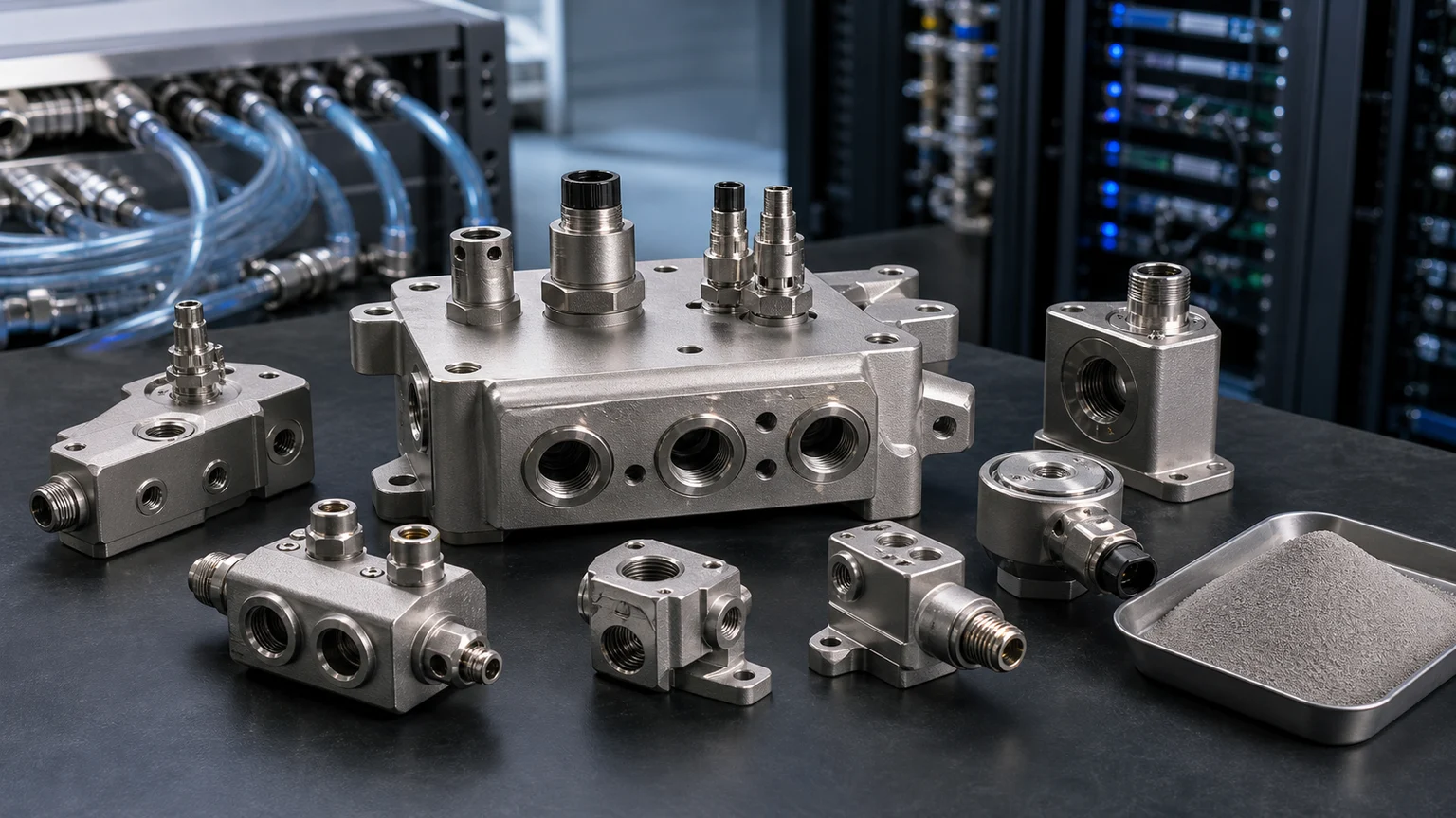
The recurring engineering problem is clear: AI racks will keep changing, but liquid-cooling loops will keep asking the same engineering questions. How should coolant be distributed? Where should sensors sit? Which bodies need stainless corrosion behavior? Which faces need machining? What powder specification and inspection route make the part repeatable?
Why AI liquid cooling creates a stainless manifold problem
Liquid-cooled AI infrastructure pushes more thermal work into the rack and into the technology cooling system. That creates many parts that are not cold plates but still sit in the coolant path. Examples include:
- coolant distribution manifold blocks near a rack or CDU
- rack-drop interface bodies
- sensor housings for pressure, temperature, and flow monitoring
- bypass or balancing manifolds
- compact transition blocks between tubing, hoses, and cold plates
- small stainless fluid-path housings used in test fixtures or pilot deployments
These parts usually do not need the thermal conductivity of CuCrZr. They need controlled stainless routing, leak-aware interfaces, stable machining, and corrosion behavior that fits the coolant chemistry. This makes the topic different from the existing CuCrZr AI cold plate and GPU manifold page, which is about copper-family thermal hardware.
The stainless side is more about distribution and control. A 316L manifold may need several ports in a small envelope, sensor bosses in the right locations, mounting ears, seal lands, and internal passages that would require multiple drilled blocks or welded assemblies in a conventional route.
Where 316L powder can fit
The best 316L candidates are parts where LPBF changes the fluid path or packaging. Useful cases include:
- compact coolant distribution manifolds with several angled branches
- sensor blocks with integrated pressure or temperature ports
- stainless transition bodies for rack-level liquid-cooling interfaces
- leak-test fixtures and development manifolds for new cold-plate layouts
- small CDU-side blocks where routing, mounting, and instrumentation overlap
- clean stainless housings that need post-machined sealing faces
The common pattern is not “AI data center” by itself. The common pattern is routed stainless fluid hardware. That is why this page connects directly to the broader 316L manifolds and fluid-path parts guide. The AI data center context adds higher density, more monitoring, and a faster iteration cycle, but the powder decision still starts with the part’s fluid duty.
Where 316L should not be forced
316L powder should not be treated as a universal liquid-cooling material. If the part is the primary heat-transfer surface under a GPU, accelerator, ASIC, or optical module, a copper-family route may be more relevant. That is where CuCrZr powder for cold plates and CuCrZr powder for co-packaged optics cold plates are closer fits.
If the coolant or process environment is more chemically aggressive than ordinary inhibited water, water-glycol, or compatible dielectric-loop hardware, the material review should become more conservative. Chlorides, poor coolant control, galvanic pairings, cleaning chemistry, and high-temperature exposure can change the answer. In some cases, a nickel alloy route or a different stainless specification may be cleaner. The 316L vs nickel powder comparison for corrosion-side manifolds is the better starting point when corrosion severity is the real risk.
If the part is strength-first, 17-4PH may deserve review. But for many coolant distribution manifolds, corrosion-aware stainless behavior and fluid-path stability matter more than precipitation-hardening strength.
Why LPBF changes the manifold design
LPBF does not make a bad manifold good. It changes which manifold geometries are practical. A printed 316L coolant block can combine features that would otherwise require several drilled parts, plugs, welds, or brazed joints.
Potential LPBF advantages include:
- shorter internal routing with fewer external fittings
- angled branches that avoid awkward cross-drilling
- integrated sensor bosses and mounting pads
- smoother transitions where flow balance matters
- compact packaging around rack-side service envelopes
- test articles that can evolve faster than machined manifold stacks
The same freedom can create problems if it is not controlled. Blind internal cavities can trap powder. Sharp turns can make inspection difficult. Unsupported features can distort. Ports and seal lands still need machining stock. Leak-critical walls need density control and validation. A useful design review should treat the powder route, build orientation, support strategy, cleaning path, machining plan, and leak test as one workflow.
Powder specification details that matter
For 316L LPBF coolant hardware, the powder discussion should stay specific. A useful RFQ should identify:
- process route, usually LPBF for compact routed manifolds
- particle-size range, commonly 15-45 um or 15-53 um depending on machine and supplier
- chemistry limits and lot traceability
- oxygen and contamination control
- morphology, flowability, and apparent density expectations
- powder reuse policy if recurring production is planned
- heat treatment or stress-relief route
- post-machined faces, ports, O-ring grooves, threaded features, and sensor seats
- pressure, leak-test, cleaning, and passivation expectations
The LPBF powder particle size guide is useful for the process-side range discussion. The metal powder specification guide is better for PSD, oxygen, flowability, and COA language.
Design checklist for AI cooling manifolds
A 316L coolant distribution manifold should be designed around the acceptance path, not only the printed shape. Before asking for powder or part quotation, define:
- coolant type and inhibitor package
- operating pressure, proof pressure, and leak-test method
- flow rate and pressure-drop target
- port standard and machining allowance
- seal type, O-ring groove design, and surface finish requirement
- sensor locations and wiring/service access
- minimum wall thickness around internal channels
- powder removal access and cleaning method
- whether internal surfaces need polishing, passivation, or only controlled cleaning
- galvanic contact risks against copper, aluminum, or plated hardware
- whether the part is a prototype, validation article, or recurring production component
A printed 316L manifold still needs engineering validation, including the specified machining, pressure and leak tests, chemical compatibility review, and inspection. AM does not eliminate these steps; its value must come from a compact, cleanable fluid path that conventional drilling or assembly cannot deliver as effectively.
How it connects to existing material choices
For a liquid-cooled AI rack, a practical material map often looks like this:
| Hardware area | Common material direction | Powder-page path |
|---|---|---|
| Cold plate or heat-transfer core | Copper-family route where conductivity matters | CuCrZr AI cold plates |
| CPO or optical thermal hardware | Copper-family route for dense local cooling | CuCrZr CPO cold plates |
| Coolant distribution and sensor blocks | 316L when routed stainless behavior is enough | This 316L coolant distribution page |
| Clean gas or sensor-adjacent stainless hardware | 316L if clean routing and sealing dominate | 316L semiconductor gas manifolds |
| More aggressive corrosion-side manifolds | 316L vs nickel review | 316L vs nickel powder |
Choose the material for the component’s function: heat transfer, coolant containment, structural support, or electrical conduction. Then verify coolant compatibility, surface condition, cleaning, joining, pressure, and leak requirements for the complete assembly.
Related guides for the topic
If the project is starting from the application, use the AI Liquid Cooling hub to compare copper and stainless thermal-fluid hardware. If the project is starting from the material, use the Stainless Steel Powder hub. If the main question is manufacturability, route through LPBF Powder.
For adjacent stainless paths, continue with 316L powder for manifolds and fluid-path parts, 316L powder for semiconductor gas manifolds and sensor housings, or 316L powder for hydrogen electrolyzer flow-field hardware depending on the actual environment.
The practical takeaway
Use 316L powder for AI data center coolant distribution manifolds when the part is a routed stainless fluid-path problem: compact channels, sensor integration, seal lands, rack-side serviceability, and corrosion-aware coolant compatibility. Do not use it as a blanket substitute for copper cold plates or for aggressive corrosion environments without testing.
The strongest 316L AI cooling case is not a generic manifold. It is a compact, leak-aware, instrumented stainless block where LPBF reduces assembly complexity and creates a cleaner fluid path than drilling, plugging, welding, or stacking several conventional parts.